Our Mitsubishi Ecodan PUHZ-HW140VHA2-BS 14kW heat-pump was installed in 2011 with an FTC2 control unit when this house was built.
Upstairs and downstairs heatmiser UH1 manifolds are controlled by room thermostats, these are connected together using an RS485 bus.
The PC software provided by heatmiser turned out to be written for a 32bit Windows 7 PC and required an ethernet to RS485 bridge to work;
this never worked satisfactorily, so when I redeveloped the home automation system in 2017 I included server software to interface to
Heatmiser's specification. This enabled schedules to be set for the room thermostats.
Room thermostats provided a means of controlling when the heatpump runs.
Over the years a schedule for running it has evolved, based on very little information and control via heatmiser room thermostats.
Hot water was controlled via a conventional time-clock programmer as with a gas boiler.
The remote control unit, which includes a zone thermostat was installed next to the heating cylinder where any temperatures measured were useless.
What was the replacement
Towards the end of 2024 the HP installer was presented with a requirement to:
Have heat generation (and electricity consumption) available digitally so that it could be logged.
Provide better control over hot water.
Control the system digitally.
Move the remote control unit to a useful central position (main room).
Consolidate all mains circuits associated with the HP on the same circuit (so that electricity measurement includes all controls).
Provide digital information about the solar hot water system.
For further information about the technical detail of the installation see heating upgrade
An upgrade to a Mitsubishi FTC6 controller was suggested, which was taken up.
Most users would probably have gone for installing an interface to MelCloud, which enables control via a phone app.
I didn’t do this as:
Cloud servers have a few weaknesses so are avoided:
Do not work if broadband fails
Dependent on manufacturer to continue support.
Each manufacturer follows different standards
Unknown (hidden) energy use
Prone to attack from bad actors
Just way over complicated for storage of simple sensor readings.
It would prevent a direct data feed.
All home data in a single system, rather than a proliferation of apps.
A MODBUS interface is available which was fitted instead, this gave the opportunity to either:
Fit a third party unit with its own cloud based software (the fallback position)
Write a MODBUS interface which publishes data to an MQTT broker. (MQTT has been adopted by many home automation systems).
The result is that I have been logging Modbus data to a Questdb database since late november.
Since then daily graphics have been available to see how the HP is performing.
What has been learned?
Controlling the HP using using room thermostats leads to cycling which reduces heat output and still uses a similar amount of electricity.
So I am now setting room thermostats in main rooms well above what is likely to be reached,
relying on the flow temperature setting in the HP, which is on Weather Compensation.
HP gives enough data to calculate heat loss rate and degree days.
There is little point in trying to heat difficult to heat rooms (lean-to and main bedroom) outside the main schedule.
Ideal heating periods are long and unbroken.
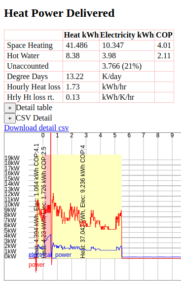
Example Good Heating session
The table to the left shows summary analysis of 25 hours starting at 23:00 on 14th Jan. and ending at 00:00 on 16th Jan.
This covers 15th Jan completely and includes the end of the previous day because cheap rate electricity is available from 23:30
The summary table at the top shows:
Space heating - heat produced, electricity consumed, COP being the ratio of these
Hot water - heat producedm electricity consumed and COP
Unaccounted - Electricity reported as consumed by the heatpump when it is idle (currently some of this is suspected as a measuring error)
Degree Days - Heat produced divided by the mean difference between room temperature and ambient temperatur
Hourly Heat Loss - Heat produced divided by time
Hourly Heat loss rate - Heat produced divided by time and the mean temperature difference
The Detail table button reveals a table showing details for each heating session
CSV Detail shows the same as detail table, but in a csv format which pastes well into a spreadsheet
The graph below shows:
Red line shows heat power in kW
Blue line shows electrical power consumption in kW
Solid yellow shows space heating periods
Pink and purple show hot water periods (purple shows where these are forced).
Continuous heating session
Here heating runs continuously between 23:30 and 05:30 (taking advantage of Octopus IOG).
Ambient temperature between 6 and 8 C, flow temperature between 32.5C and 36C.
Hot water heating follows on directly from other heating so there is no initial temperature drop and a reasonable COP of 2.5 is achieved
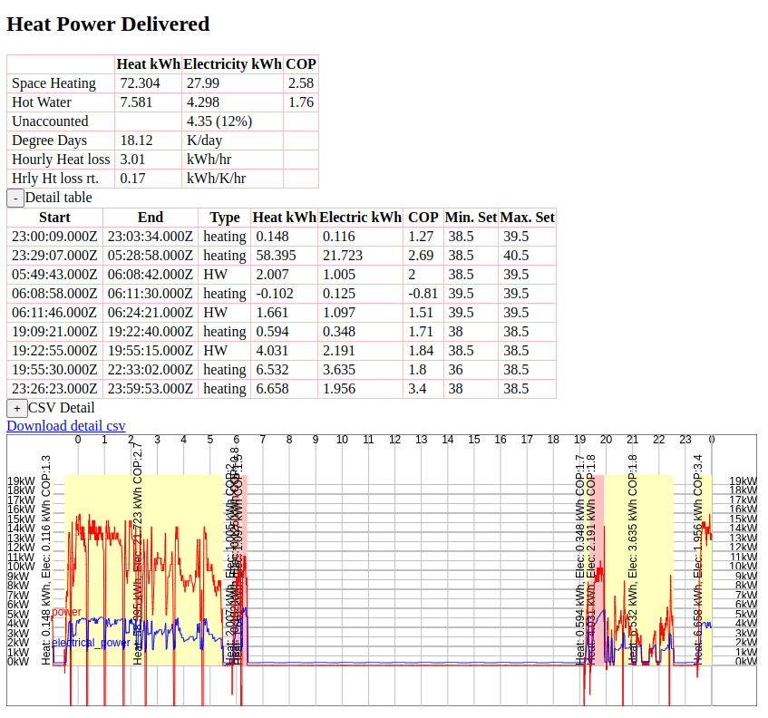
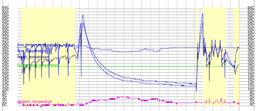
Example Bad Heating session in cold weather
Here the ambient temperature at night was 0C and it was cold all day.
The flow temperature was higher (see table above)
Heating sessions later in the day were triggered by the lean-to and main bedroom temperatures dropping below their room thermostat settings.
The flow temperature seems to hit the flow temperature set point and cause the HP to shut down for a short period before starting again.
To what extent does this reduce COP?
Note that the good session had a heat output of 41kWh, whereas the main session here had 58kWh.
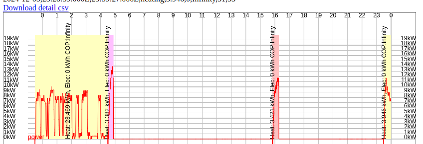
In high temperatures
Example from 5th December before electricity readings were available, with ambient temperature 12C shows cycling with flow temperature 29C.
About 27kWh of heat was produced.
What didn’t go so well
Initial software development
This project is part of a larger project to redevelop the Oakhouse home automation system,
aimed at bringing it up to date, making it easier to maintain, and reducing energy consumption,
and make all elements supportable using Ubuntu Linux.
This is being written up separately, as it has had its fair share of issues, which are not relevant to a HP interest.
Electricity Readings
I had thought that simply installing a split core current transformer (CT) to measure current, and from this power and energy would be good enough.
This has been fraught with problems:
Software problems prevented electricity readings from working until Jan 5th.
Though electricity whilst heating is credible, an idle current of about 1.1A is reported, at first this was thought to be a software issue.
But I have now measured it with 2 alternative methods:
Efergy E2 meter borrowed from TECs
True RMS Mini-clamp meter
Also I have used this CT on other circuit and it roughly matches readings from the others.
There is space in our consumer unit for a direct meter on the HP circuit, (the circuits used previously for CCTV and FTC2 (hp controller) are no longer used), these slots could accommodate a DIN rail direct meter, with MODBUS interface.
This may (or may not) give different readings.
Hot Water
It is disappointing that the FTC6 doesn’t support timed based scheduling of hot water,
but it does have a Force DHW flag, which turns on water heating, but it won’t turn off until its target temperature is reached.
This has just meant that a scheduled job has been written to ensure water is heated at 4:30 which is in the middle of the heating schedule,
and also fits the electricity tariff.
Update 17th October 2025
I have discovered that there is a scheduled mode for both heating and hotwater,
its just that the manual doesn't give a good explanation.
This video from Enviro Heating gives a good explanation of how to do it.
I have now set a schedule to heat water between 4:30 and 5:30 in the morning only, which leads to a further problem.
In order to ensure that the hot water only ran when scheduled, I allowed the temperature to drop by 14C before it kicked in.
The problem is the temperature drop is a readonly attribute in the modbus interface and the means of setting it not
covered clearly in the manual. Normally the settings menu that appears when you press the menu button only allows
you to set you to set eco/normal and legionella for hot water.
The trick to get to the temperature settings is to hold the menu button down for about 3 seconds,
when you do this you get an edit button which allows you to set temperatures.
This has enabled me to set the temperature drop to 5C (the lowest I can) and increase the set temperature to 49C,
which means that the minimum is 44C.
This list shows videos that I have found useful for changing settings on the control unit:
When this was initially written I had not installed a means of monitoring the performance of solar thermal.
A VBUS/USB converter has now been added connected to a Raspberry Pi.
The 9th October was a sunny day and saw a solar collector temperature of 66C and top of tank at 54C,
so even though water heating was scheduled it didn't occur.
Over the summer we had not needed water heating from the heatpump at all.
I had hoped that I could automate when the HW ran by setting a minimum temperature for the HP to kick in overnight,
but that would have to be done manually, so I wouldn't want to do it every day.
Possibilities:
Calculate a minimum temperature each day and adjust the tank set point to achieve that
Analyse tank temperatures from FTC6 for 2025 so far by (say) month, identify months that don't need
to schedule hot water.
In may 2026 the usb connection stopped working, most likely due to a fault in the USB hub,
and it proved very difficult to get the vbus usb device to communicate.
This triggerer me to move bridging from devices in these positions to an embedded device using C code,
using a home built interface board following the spec found in the VBUS protocol specification and feeding
via RS485 to an embedded local hub.
Update 15th July 2026
Use of a raspberry Pi linux board proved difficult to manage because:
Whenever the pi rebooted I needed to check that all scripts were working properly,
even though in theory running these as jobs under systemctl should have solved this.
USB Connections proved unreliable
USB to RS485 serial port not restoring consistently
I decided that rather than reviving the TMC1294 board which was bulky and not well supported under linux,
that I would move the C code to an implementation on a W5500-evb-pico2 board.
, developing in C for pico family boards is very well supported under linux.
At the same time I would add an EASTRON SDM120CTM meter to provide metering via modbus.
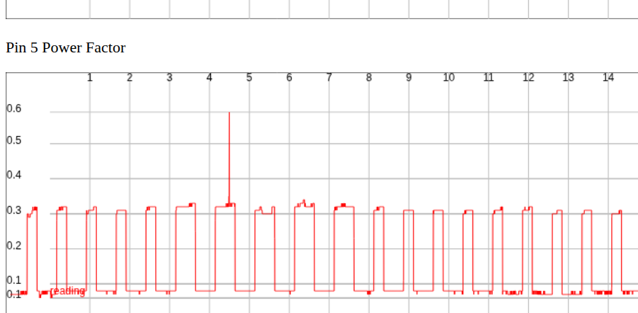
The EASTROH meter has shown that when the heatpump is idle the apparent power consumption of 250W is
mainly reactive power, with active power between 20W and 100W when idle, corresponding with a power factor
between 0.08 and 0.31. In a domestic setting only active power is metered, and inverters handle reactive power
efficiently, so that it doesn't use solar or battery energy either.
Power factor is shown in the following screenshot:
This shows a pattern of cycling between a factor of about 0.08 and 0.31.
The 0.31 periods are noticeably longer at night.
It is surmised that these correspond with:
0.08 Periods correspond with the only active consumption being control electronics
0.31 Periods correspond with additional power being used to heat the crankcase of the heat pump,
this is explained Wikipedia - Crankcase Heater
Reactive power is consumed by inductive loads such as motors and transformers.
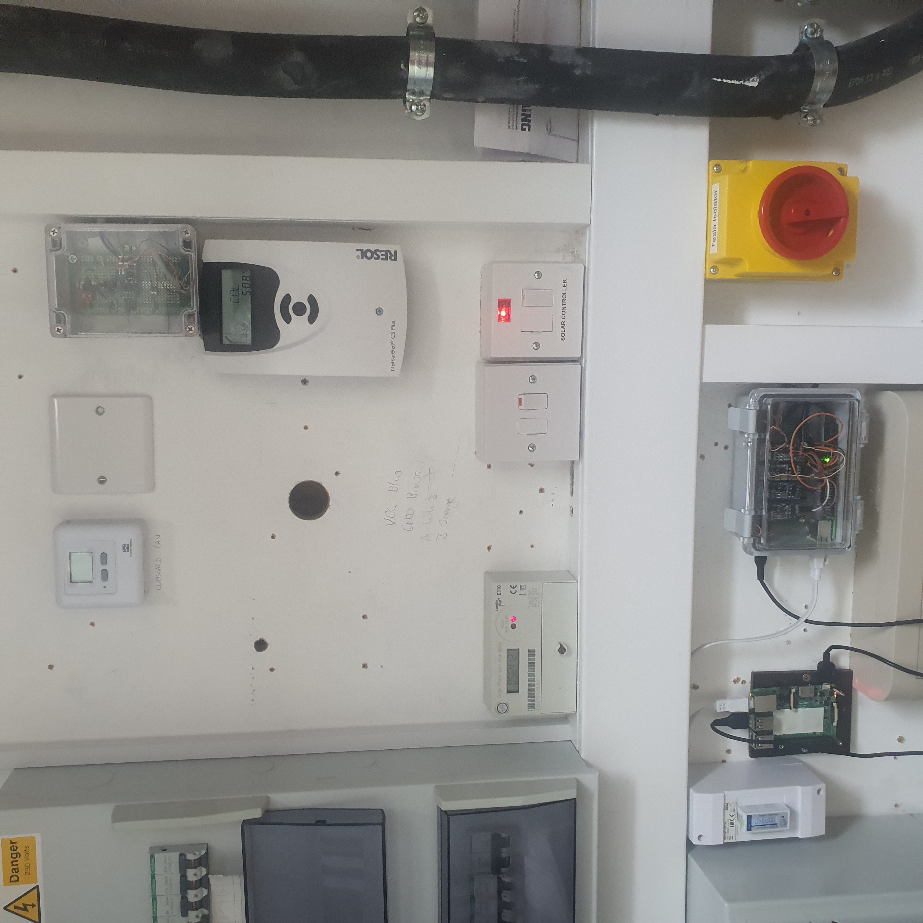
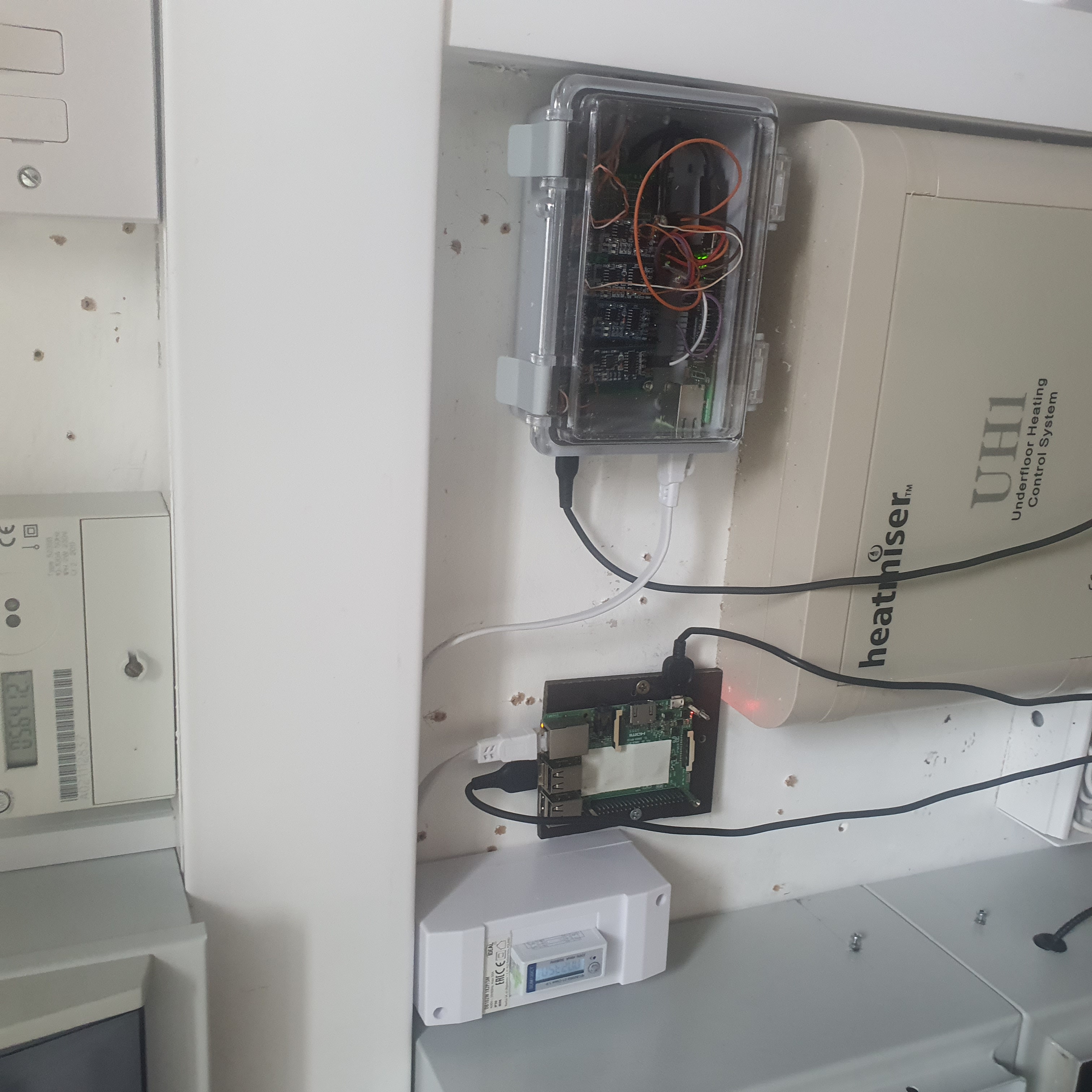
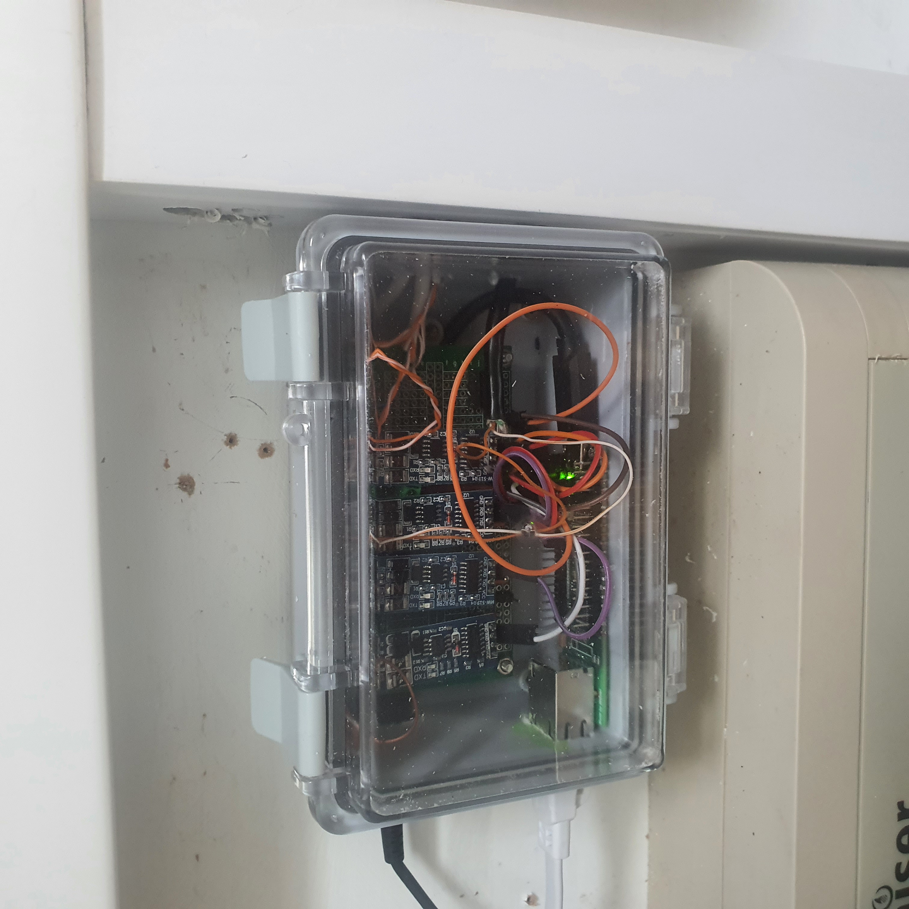
The images below shows the current setup:
Installation overviewMeter and hubRS485 - Ethernet hubResol VBUS interface
What next
Fit a MODBUS electricity meter to the HP supply. DONE
Change lean-to and main bedroom thermostat schedules to avoid low efficiency heating.
Build an insulated box around where cables emerge from floor in lean-to - known to be a big heat leak. DONE
Can thermal mass be added? E.g bricks?
From forecasts available from OpenWeatherStation produce a daily heat requirement forecast,
which can be used to schedule the HP.
Ensure that flow temperature control can be automated reliably.
Determine the best flow temperatures to use in higher temperature situations (suspect this is about 30C),
and use the forecast to determine a shorter heating period.
Determine the best flow temperature to use for high temperature situations.
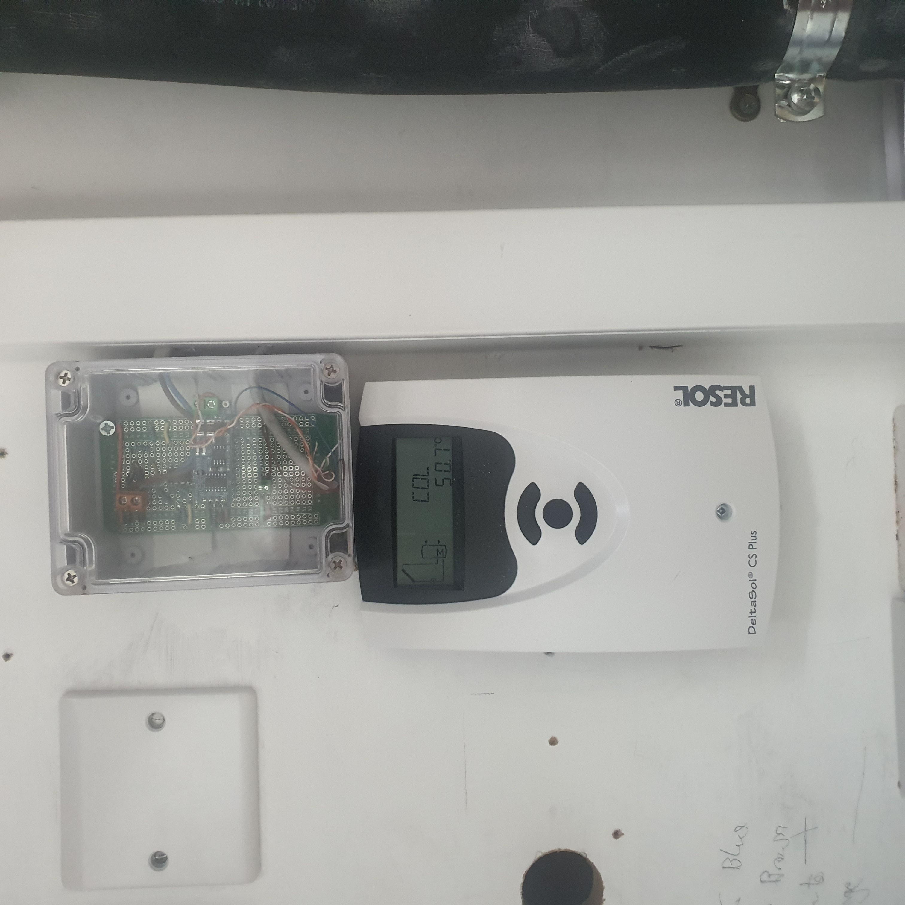
The RESOL/VELUX solar thermal controller has also been replaced with one with a VBUS feed, which needs interfacing to the TM4C board.
An ethernet convertor is available for this (£200),
but a fairly simple circuit can be built to convert to TTL serial levels which can then feed the TM4C directly.
This will provide information about solar water heating mainly in the summer.
It will also provide temperatures at the top and bottom of the hot water tank.
Update 17th October 2025 - a VBUS/USB adapter and Raspberry Pi have now been installed.
Update 15th July 2026 - VBUS/USB + Raspberry Pi replaced by home made board and W5500-evb-pico2