

| Qty | Description | Cost | Notes |
|---|---|---|---|
| 1 | Labour | Cost | |
| 1 | FTC Flow Temp Controller (PAC-IF072B-E) | 800 | Needs modbus interface |
| 1 | Flow Sensor and 28mm connections | 190 | Is this heat meter? |
| 1 | Hot Water Sensor | 30 | |
| 1 | Solar Resol Deltasol CS Plus Controller | 175 | This has VBUS output |
| 1 | Solar Controller KS2 Communication module | 220 | NO Consider other options |
| 1 | 28m Magnetic Filter | 150 | |
| 1 | 6m X 2.5mm 3 core Sy Cable | 18 |
To get data from the FTC to RS485 (and thus to anything else) we need Procon MelcoBEMS MINI A1M a possible source of this is Mitsubishi Electric Procon MelcoBEMS MINI A1M
P9 - Calculation internally
Electricity consumption is calculated internally based on the energy consumption of outdoor unit, electric heater, water pump(s) and other auxiliaries. Delivered heat is calculated internally by multiplying delta T (Flow and Return temp.) and flow rate measured by the locally supplied sensors. Set the electric heater capacity and water pump(s) input according to indoor unit model and specs of additional pump(s) supplied locally. (Refer to the menu tree in “7.2 Main remote controller”)
Quote includes flow meter and temperature sensors, so heat energy is calculated from this.
For more accuracy a flow meter would be needed, together with electricity meters.
2. Actual measurement by external meter (locally supplied) FTC has external input terminals for 2 ‘Electric energy meters’ and a ‘Heat meter’. If two ‘Electric energy meters’ are connected, the 2 recorded values will be combined at the FTC and shown on the main remote controller. (e.g. Meter 1 for H/P power line, Meter 2 for heater power line) Refer to the [Signal inputs] section in “4.5 Connecting inputs/outputs” for more information on connectable electric energy meter and heat met
To provide the best efficiency Mitsubishi Electric recommends using automatic adaptation function based on room temperature. To use this function a room thermistor needs to be present in a main living area. This can be done in a number of ways the most convenient are detailed below.
IN11, IN12 are smart grid ready inputs see 4.9
| IN11 | IN12 | Meaning |
|---|---|---|
| OFF(open) | OFF | Normal Operation |
| ON | OFF | Switch-on recommendation |
| OFF | ON | Switch-off command |
| ON | ON | Switch-on command |
This contains a thermistor which can be used in Control option C P16 of FTC6 Installation Manual, which can be used to set a desired room temperature.
This would be more useful in a living room with typical room temperature, possibly in place of, or as well as by the light switch between the study and leanto.
The FTC6 installation manual P12 & 13 describes installation of the main remote control. This describes a 2 X 0.3mm2 wire to connect the controller to the FTC6 unit, rated to carry 12VDC. (not always wrt ground)
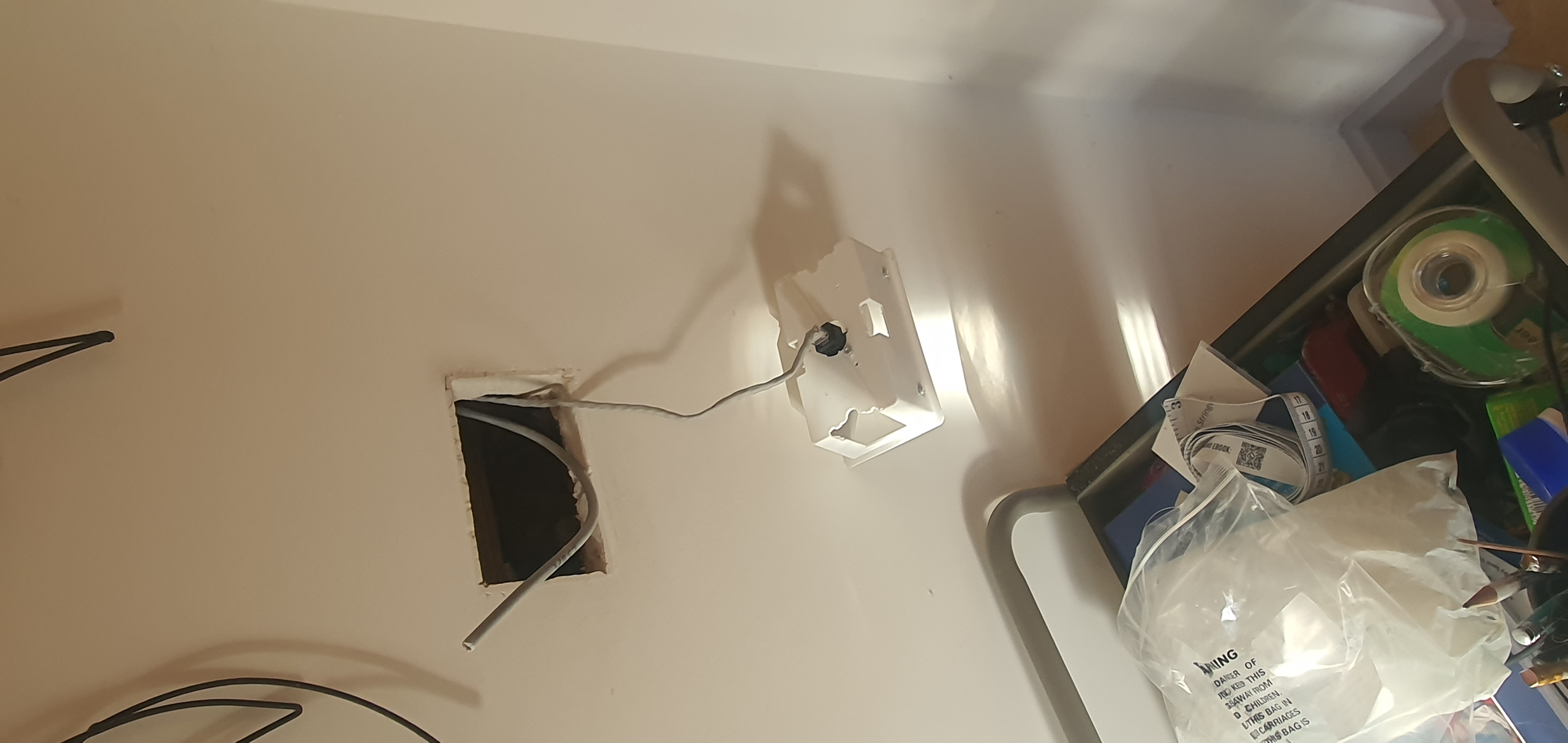
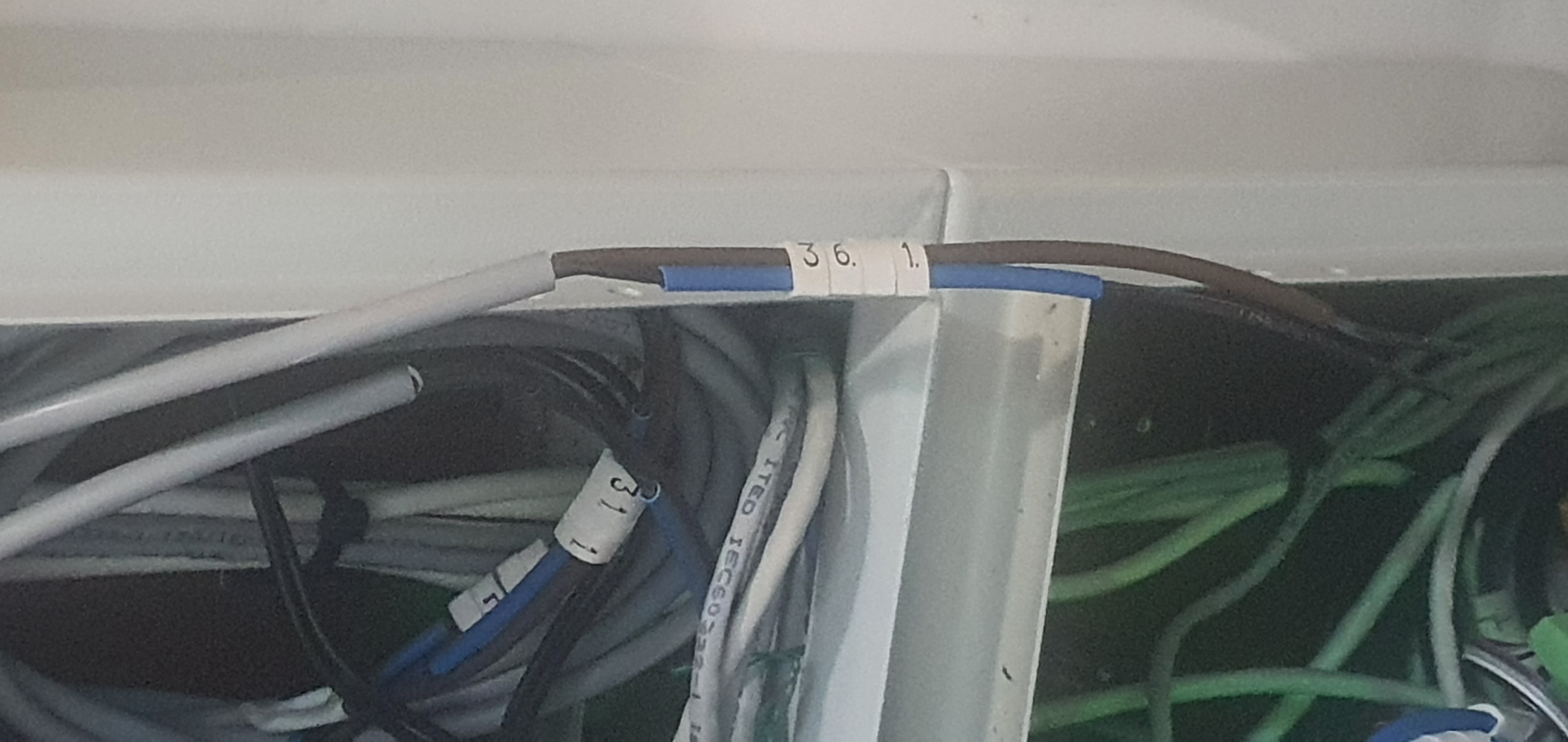
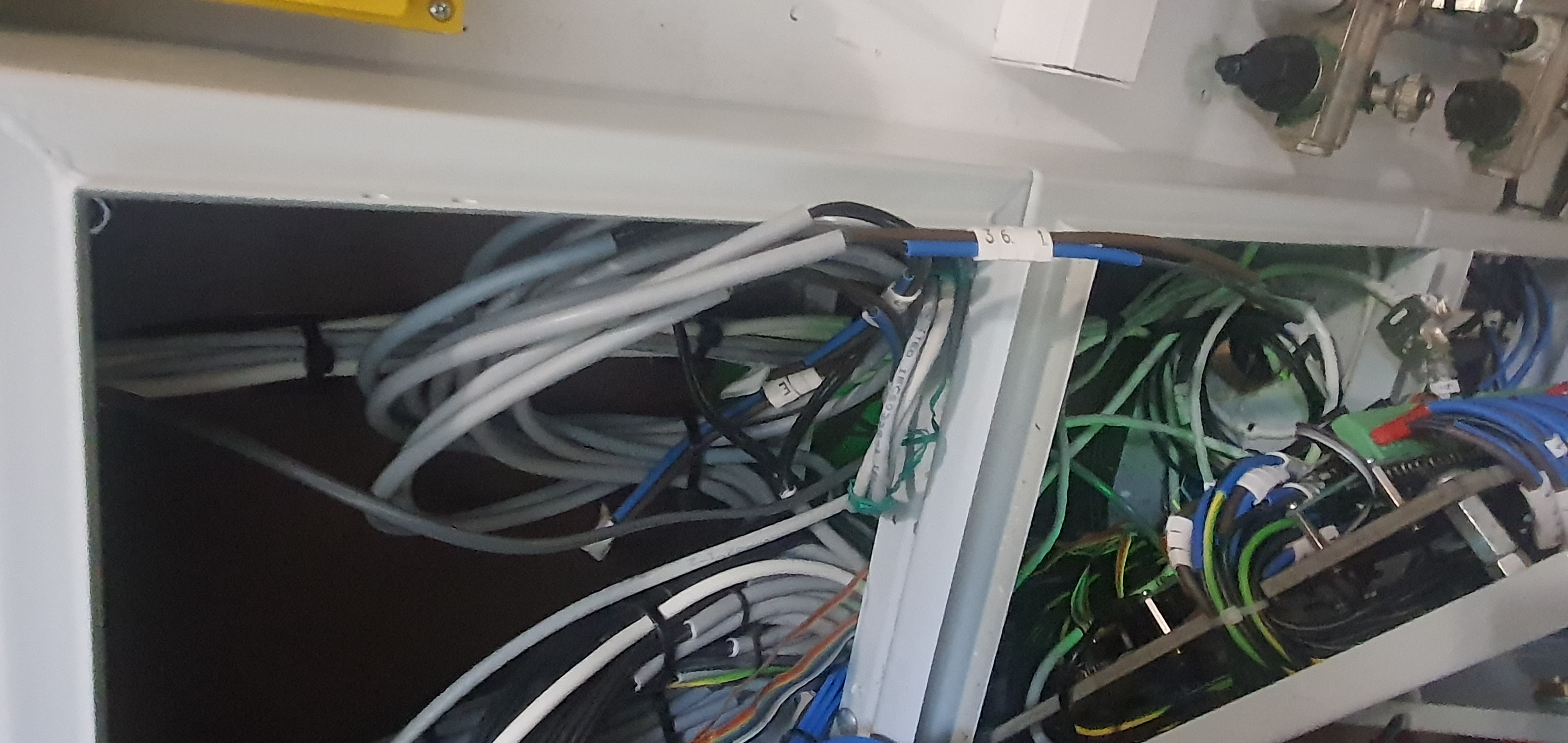
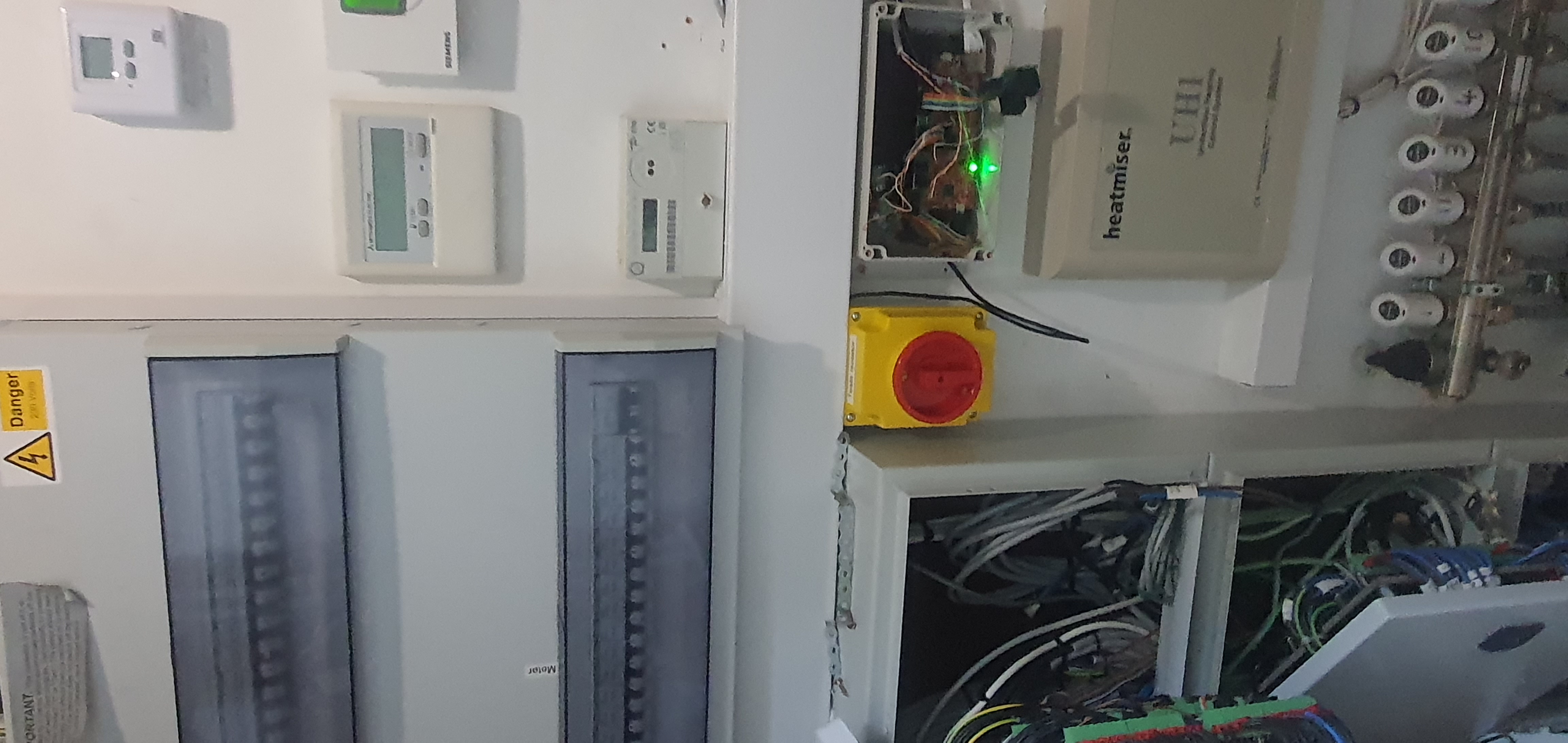
At the the light switch position there is a 12VDC cable which might be suitable. This is labelled L36/1 and goes from the light switch position to the top lighting control cabinet. Could this be joined to the cable going to the FTC6.
 |
 |
 |
 |
There are some posible locations near light switches that have 12VDC cables going to Position A:
Darren has suggested
Reading the installation manual it is apparent that a MELCOBEMS Mini is needed to provide a Modbus RTU slave node.
The pros and cons of this are:
Pros:
Cons:
BACNet MS/TP is a master slave token passing network for transferring data from devices to controllers.
It is apparent that Modbus is the only practical protocol for communication with the FTC6 via MELCOBEMSMini.
This is a fairly simple circuit to convert VBUS signals to UART
VBUS is a signal between -8.2V and +8.2V which can be converted to UART by a simplish circuit. The converted signal is at 9600baud 1 start, 8 data and 1 stop bit
References:
In order to calculate COP we need to measure input power. There is a 1V=50A CT around the heatpump power supply (40A fuse). The current plan is to measure current with the TM4C board, fitted with suitable conditioning resistors. Does FTC6 need a CT feed?
Just found this direct connection to CN105, which might be simpler if modbus to MQTT proves difficult:
With the old FTC2 hot water heating was triggered via an old fashioned programmer, there was one setting on the remote unit for hot water target temperature. With this I had ended up with an hour long slot between 3:30 and 4:30 in the morning, and a maximum temperature of 48C. This meant that on a day with no solar thermal, the temperature could drop to under 30C by the end of the period.
The FTC6 is more sophisticated in its control of hot water with:
The initial setup had maximum temperature 48C and a drop of 6C to 42C, this gave the impression of permanent hot water, but with 4 heating periods per day.
| Address | Name | Notes |
|---|---|---|
| 40031 | Tank Set Point | this is the temperature that the HP turns off when heating water |
| 40038 | Force DHW | Forces water to heat by turning the three way valve to water |
| 40092 | DHW Temperature Drop | Amount below Tank Set Point that tank temperature can drop before heat pump turns on |
| 40102 | Flow Temperature | The temperature of water entering the circuit from the heat pump |
| 40104 | Return Temperature | The temperature of water returning from the circuit to be heated |
| 40106 | Tank water temperature | The temperature of water in the centre of the tank |
| 40128 | Heat pump master switch | Set when the heat pump is on |
| 40153 | Tree Way Valve | Valve diverts heating water flow to the hot water tank |
| 40300 | Flow Rate | Flow rate in Litres / minute |
| 40343 - 48 | Timestamp | Current time in 6 fields Year, Month, Day, Hour, Minute, Second |
These together with some additional values used for space heating are recorded in the database in the ftc_performance table at intervals of about a minute.
From these we can derive:
A Typical water heating session start by either:
This means that to determine if the heatpump is being used to heat water several rows at the start of a heating session may need to be examined. This is done by grouping succesive rows with either the heatpump_on flag or the three_way_valve flag set. If any of those sessions has the three_way_valve flag set, then the session is classified as hotwater, otherwise it is classified as space heating.
Note this method has proved adequate so far, but it is conceivable that the heatpump stays on for space heating after the three way valve has closed.
We want to
In addition to the values given in the table above:
| Address | Name | Notes |
|---|---|---|
| 40033 | H/C Target Temperature- Zone 1 | This is settable and appears to always be equal to the set flow temperature |
| 40041 | Heating on prohibit | This might be useful to turn the heating off, say when incentivised to do so |
| 40055 | Thermostat Target Temperature Zone 1 | aka Set Room Temperature |
| 40082 | Temperature Set Point Zone 1 | appears to be the same as 40055 but readonly |
| 40086 | Flow Temperature Set Point | appears to be the same as 40033 but readonly |
| 40094 | Room Temperature Zone 1 | Measured from remote control unit |
| 40100 | Outdoor Ambient Temperature | Temperature from sensor on HP outside unit |
This is made from the difference between room temperature and ambient temperature